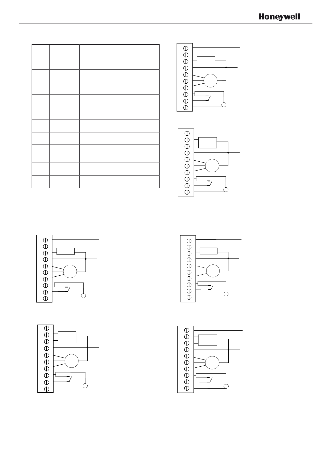
Terminal Designations
Item Terminal
Description
1
L
ACPower
2
Ch/Cc
Heating close/Cooling close
3
W/Y
Heating open/Cooling open
4
N
ACGround
5
Gh
High speed fan relay
6
Gm
Medium speed fan relay
7
Gl
Low speed fan relay
8
Sc
Ground for remote sensor and remote
setback
9
RSB
Remote set back
10
Rs
Remote sensor
Wiringdiagrams
Application 1: 2 pipes heat onlywiring diagram
Application 2: 2 pipesCool onlywiring diagram
Application 3: 2 pipes 1 stage Heat or 1 stage Cool
MCOwiring diagram
APH07CH04
-
R2000EN
1
2
4
5
6
7
8
9
10
Fan
Heat valve
N
L
RemoteSensor
RemoteSetback
Typicalwiring forON/OFF control in2pipe
heating only (VC4013)
3
10
3
Typicalwiring for 3-wire control in2pipe heating only
(VC6013)
1
2
3
4
5
6
7
8
9
10
Fan
Heat valve
N
L
RemoteSensor
RemoteSetback
1
2
4
5
6
7
8
9
10
3
Fan
Cool valve
N
L
RemoteSensor
RemoteSetback
Typicalwiring forON/OFF control in2pipe
cooling only (VC4013)
1
2
3
4
5
6
7
8
9
10
1
2
4
5
6
7
8
9
10
3
Typicalwiring for 3-wire control in2pipe cooling only
(VC6013)
1
2
3
4
5
6
7
8
9
10
Fan
Cool valve
N
L
RemoteSensor
RemoteSetback
1
2
4
5
6
7
8
9
10
3
Typicalwiring forON/OFF control in2pipes
1H1C (VC4013)
1
2
3
4
5
6
7
8
9
10
Fan
Valve
N
L
RemoteSensor
RemoteSetback
9
1
2
4
5
6
7
8
9
10
3
Typicalwiring for 3-wire control in2pipes 1H1C
(VC6013)
1
2
3
4
5
6
7
8
9
10
Fan
Valve
N
L
RemoteSensor
RemoteSetback
1
2
4
5
6
7
8
9
10
3


