Mechanical design
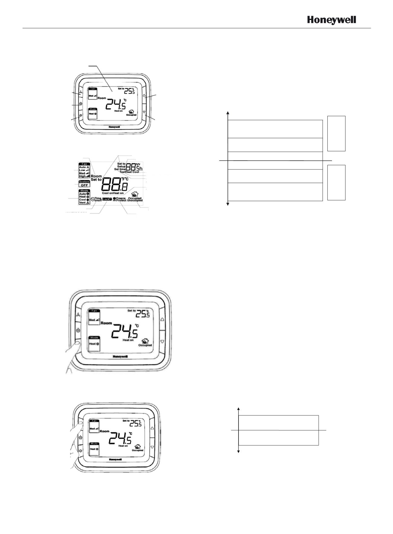
Thermostat appearnce
LCDdisplay
Function
Valve control
Thermostat acquires the room temperature via its
integrated sensor or external temperature sensor
andmaintains the setpoint by delivering on/off valve
control commands output.
FanOperation
DIGITALDISPLAY
FANBUTTON
POWERBUTTON
MODEBUTTON
UPBUTTON
DOWNBUTTON
INDICATESROOMTEMPERATURE
CURRENTFANSETTING
INDICATES THERMOSTAT IS
OFF
CURRENT
MODESETTING
INDICATESTHERMOSTAT
ISSETTOTIMEON/OFF
INDICATESTHEKEYPAD
ISENTIRELYORPARTLY
LOCKED
INDICATESTHERMOSTAT IS
INFREEZINGPROTECTIONMODE
INDICATESWHETHER
THERMOSTAT IS INOCCUPIED
ORNOT
INDICATESTHERMOSTAT IS
"CALLING" FORHEATORCOOL
INDICATESTHE LENGTH
OFTIMEON/OFF
INDICATES THE HEAT/COOL
SETPOINT
INDICATES INSTALLERTEST
INDICATES INSTALLERSETUP
INDICATESTHESETPOINT
PRESS THE MODE BUTTON TO SELECT
HEAT, COOL,AUTOORVENT
PRESS THE FAN BUTTON TO SELECT LOW,
MED, HIGHORAUTO
Fan can be selected as manual or automatic
3-speed operation. In Manual mode, the fan
is switched to the selected speed via control
output Gh, Gm, Gl. While in automatic mode, fan
speed depends on the difference between room
temperature and setpoint. When room temperature
reaches setpoint, valve will be closed and
meanwhile, fanwill be closed either.
Four-pipe application
System will have a fixed deadband set in ISU
betweenheatingand cooling setpoints forAutomatic
Change Over (ACO) configured thermostats.While
the heating and cooling set points determine the
dead band.
If the difference between heating and cooling
set points is less than the dead band set in ISU,
then the dead band set in ISU is enforced. When
adjusting the cooling set point, conflicts will be
resolved by moving the heating set point out
of the way of the cooling set point (heating set
point=cooling set point –dead band set in ISU).
When adjusting the heating setpoint, conflicts will
be resolved by moving the cooling set point out
of the way of the heating set point (cooling set
point=heating set point +dead band set in ISU).
Heating and Cooling range stops will determine the
maximum heating setpoint setting and minimum
cooling setpoint setting.
APH07CH04
-
R2001EN
Fan speed ramping control algorithm
-4F
-2F
2F
4F
COOL
HEAT
Fan speed is highor off
Fan speed ismediumor off
Fan speed is lowor off
Fan speed is lowor off
Fan speed ismediumor off
Fan speed is highor off
Setpoint
DifferencebetweenRTandSP
4pipes auto changeover setpoint algorithm
Deadband
-1/2Deadband
+1/2Deadband
CoolingSetpoint
HeatingSetpoint
The last system control mode used will determine
themode inACOwhen in the deadband.


