Application 3: 2 pipes 1 stage Heat or 1 stage Cool
MCOwiring diagram
Application4: 4pipes 1stageHeat and1 stageCool
MCO/ACOwiring diagram
Application 2: 2 pipesCool onlywiring diagram
Installation&Commissioning
1Pull wires throughwire hole.
Loosen screw terminals, insert wires into terminal
block, then retighten screws.
2Push thePower box into the junction box.
N
L
1
2
3
4
5
6
7
8
9
10
11
12
1
2
4
5
6
7
8
9
10
11
12
3
Cool valve
Fan
RemoteSetback
RemoteSensor
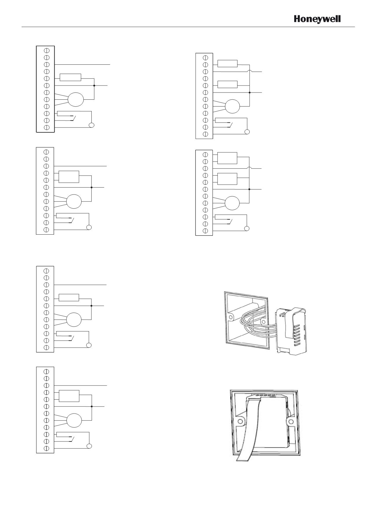
Typical wiring for ON/OFF control in 2 pipe cooling
only (VC4013)
1
2
3
4
5
6
7
8
9
10
N
L
11
12
1
2
4
5
6
7
8
9
10
11
12
3
Cool valve
Fan
RemoteSetback
Typical wiring for ON/OFF control in 2 pipe cooling
only (VC6013)
RemoteSensor
1
2
3
4
5
6
7
8
9
10
N
L
11
12
1
2
4
5
6
7
8
9
10
11
12
3
valve
Fan
RemoteSetback
RemoteSensor
Typical wiring for ON/OFF control in 2 pipe heating
only (VC4013)
1
2
3
4
5
6
7
8
9
10
N
L
11
12
1
2
4
5
6
7
8
9
10
11
12
3
valve
Fan
RemoteSetback
RemoteSensor
Typical wiring for ON/OFF control in2 pipe heating
only (VC6013)
1
2
3
4
5
6
7
8
9
10
N
L
11
12
1
2
4
5
6
7
8
9
10
11
12
3
Fan
RemoteSetback
RemoteSensor
Cool valve
Heat valve
Fig.2.7 Typical wiring for ON/OFF
c
ontrol in 4 pipe
1H/1CAuto/ Manual Changeover (VC4013)
1
2
3
4
5
6
7
8
9
10
N
L
11
12
1
2
4
5
6
7
8
9
10
11
12
3
Fan
RemoteSetback
RemoteSensor
Cool valve
Heat valve
Typical wiring for 3-wire control in 4 pipe 1H/1C
Auto/ Manual Changeover (VC6013)
APH07CH04
-
R2001EN
l iring for ON/O F control in 2 pipe 1H1C
(VC4013)
l iring for ON/O F control in 2 ipe 1H1C
(VC6013)


