APEN0H-028CH33A0308
3
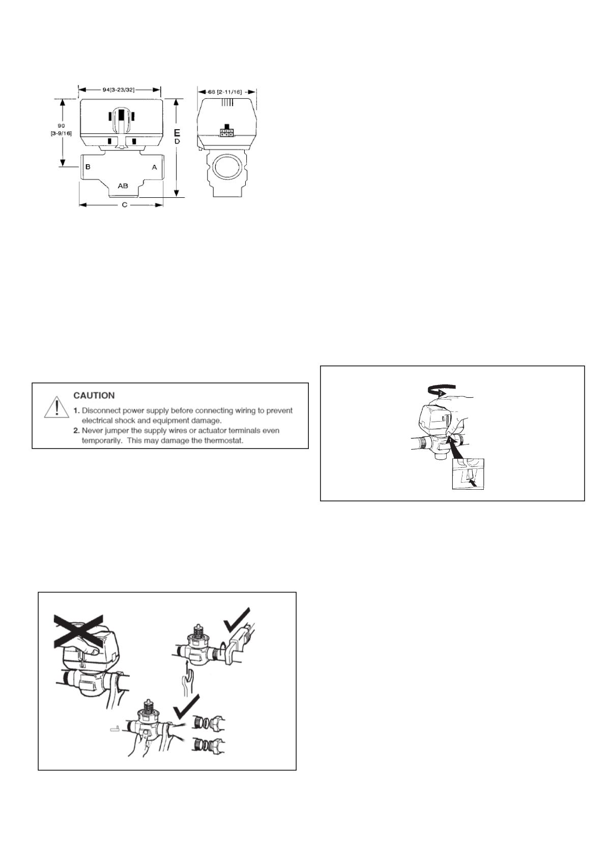
Fig.4– 3-way nominal dimensions in inches andmillimetres
INSTALLATION
WHEN INSTALLINGTHISPRODUCT:
1
.
Read these instructions carefully. Failure to follow them could
damage the product or cause ahazardous condition.
2. Check the ratings given in the instructions and on the product to
make sure the product is suitable for your application.
3. Installermust be a trained, experienced service-person.
4. Always conduct a thorough check-out when installation is
completed.
5. Whilenot necessary to remove the actuator from thebody, it can
be removed for easeof installation. The actuator canbe installed
in any of the four orientations to suit themost convenient wiring
direction. Actuator latchingmechanismworks onlywhen the lengths
of theactuator and the valve bodyare parallel toeach other.
6. Anextra 25mm head clearance is required to remove the actuator.
PLUMBING
The valvemay be plumbed inanyangle but preferably not with theactuator
belowhorizontal level of thebody.Make sure there is enough room around
the actuator for servicing or replacement.
For use in divertingapplications, the valve is installedwith the flowwater
entering through bottom port AB, and diverting through end portsAor B.
Inmixing applications the valve is installedwith inlet toAor Band outlet
throughAB.
Mount the valve directly in the tube or pipe. Donot grip theactuator
whilemaking and tighteningup plumbing connections. Either hold valve
body in your hand or attach adjustable spanner (38mm or 1-1/2") across
hexagonal or flat faces on the valve body. (Figure 5)
TO INSTALLREPLACEMENTACTUATOR
IMPORTANT
Installationof anew actuator does not requiredraining the
system, provided the valvebody and valve cartridge
assembly remain in thepipeline.
1. Check replacement part number and voltage ratings formatch
witholddevice.
2. Disconnect power supply before servicing toavoidelectrical shock
or equipment damage.
3. Disconnect leadwires toactuator.Whereappropriate, label wires for
rewiring.
4. The actuator head is automatically latched to the valve. To remove,
press up on the latch mechanism with your thumb. It is located
directly below the white manual open lever (see figure 6 below).
Simultaneously press the actuator down towards the body with
moderate hand force and turn the actuator counter-clockwise by 1/8
turn (45degrees). Lift theactuator off the valvebody.
NOTE
: The actuator can also be installed at right angles to the
valve body but in this position the latchmechanismwill not
engage
.
5. Install thenew actuator by reversing theprocess in (4).
6. Reconnect leadwires.
7. Restorepower, and check-out operation.
MANUALOPENERE
Themanual opener can bemanipulated onlywhen in the up position.
The "A" port canbemanually openedby firmly pushing thewhite
manual lever down tomidway and in. In this positionboth the "A"
and "B" ports areopen, andwith auxiliary switchmodels the switch
is closed. This "manual open" positionmay beused for filling,
venting anddraining the system, or for opening the valve in caseof
power failure. The valve canbe restoredmanually to the closed
positionby depressing thewhitemanual lever lightly and then pulling
the lever out. The valveandactuator will return to theautomatic
positionwhenpower is restored.
NOTE
:
If the valve is powered open, it cannot bemanually closed,
unless actuator is removed.
WIRING
See figure
7
for singleunit wiringdetails.
Multiple valvesmay be connected inparallel toa single controller
and transformer, up to the current ratingof the controller and
transformer
.
Fig. 5 - Plumbing theVCValve
Fig.6-LatchMechanism to detachActuator


