D17PPressure reducing valvewithbalanced seat
3
EN0H-1009GE23R0513 • Subject to change
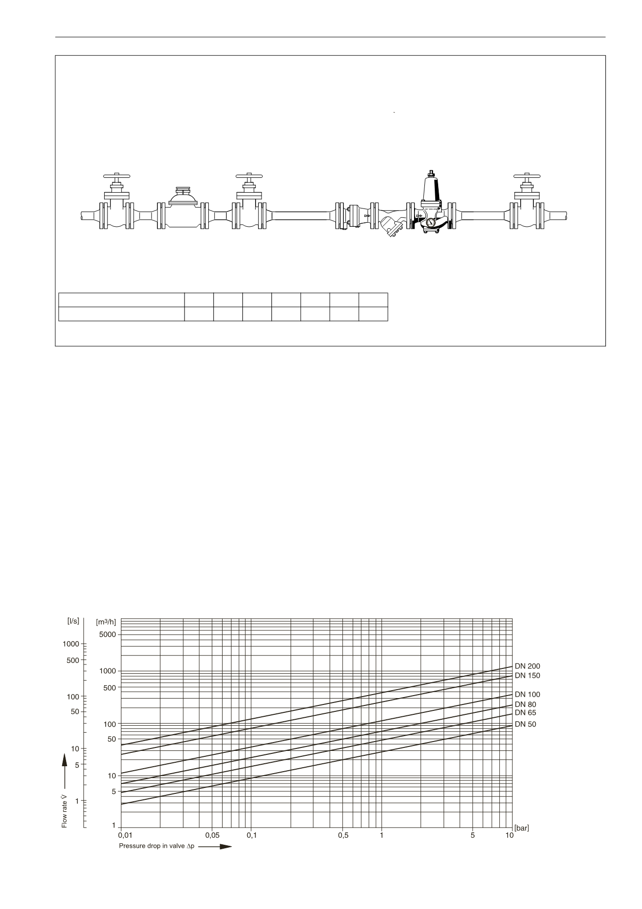
InstallationExample
Connection size
DN 50 65 80 100 125 150 200
W*
mm 100 120 130 145 165 180 220
* Minimumdistance fromwall to centre line of pipework
InstallationGuidelines
• Install in horizontal pipeworkwith springbonnet directed
upwards
• Install shutoff valves
• The installation location shouldbe protected against frost
andbe easily accessible
o Pressure gauge canbe read off easily
o Simplifiedmaintenance and cleaning
• Install downstream of the filter or strainer
o Thispositionensuresoptimumprotection for thepressure
reducing valve against dirt
• Provideastraightsectionofpipeworkofat least five times the
nominal valvesizeafter thepressure reducing valve (inaccor-
dancewithDINEN806part 2)
Typical Applications
Pressure reducing valves of this type are suitable formulti dwel-
lingbuildings, industrial and commercial applicationswithin the
range of their specifications.
Pressure reducing valves shouldbe installed:
• If thestaticpressureexceeds themaximumpermissiblevalue
for the system
• If several pressure zones are requiredwhen apressurisation
system is used (pressure reducers on each storey of a buil-
ding)
• If pressure fluctuations in the downstream systemmust be
avoided
• To achieve constant inlet and outlet pressures on pumped
pressureboosting systems
• To reduce thewater consumption
FlowDiagram


