D06FPressure reducingvalve
17
Subject tochange
EN0H-1002GE23R0900
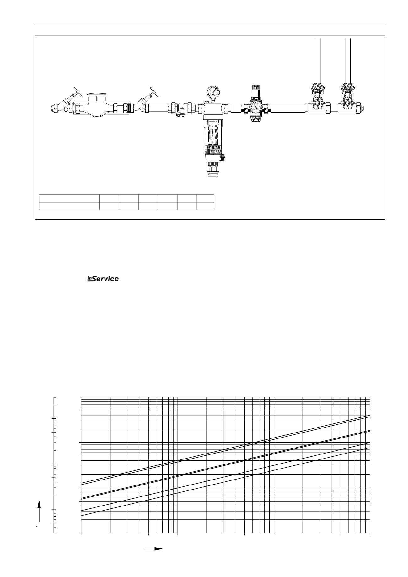
InstallationExample
0,01
[m
3
/h]
[bar]
0,05
0,1
0,5
1
10
5
FlowV
0,1
0,5
1
10
5
50
0,1
[l/s]
0,5
1
10
5
R
3
/
4
"
R2"
R 1"
R 1
1
/
2
"
R 1
1
/
4
"
R
1
/
2
"
Pressure drop in valve
∆
p
ConnectionSize R
1
/
2
"
3
/
4
"
1" 1
1
/
4
" 1
1
/
2
" 2"
W*
(mm)
55 55 55 60 70 70
*Minimum distance fromwall to centre line of pipework
TypicalApplications
D06Fpressure reducing valvesare suitable for all typesof
householdwater installations. They can also be used for
industrial andcommercial applicationswithin the rangeof their
specifications.
Pressure reducing valves should be installed:
l
If the staticpressureexceeds themaximum
permissible value for the system
l
As protection against noise if the static pressure at take
off points exceeds 5.0 bar (DIN 4109: Noise protection
inhighbuildings)
l
If several pressure zonesare requiredwhenapressuri-
sation system is used (pressure reducers on each storey
of a building)
l
If pressure fluctuations in the downstream systemmust
be avoided
l
To achieve constant inlet and outlet pressures on
pumpedpressure boosting systems
InstallationGuidelines
l
If possible install inhorizontal pipeworkwith the filter bowl
downwards
m
This is themost effective position for cleaning
l
Fit shut off valves
m
This permits
– servicing andmainten-
ancewithout removal from pipework
l
Ensure good accessibility
m
So that the pressure gauge can be easily seen
m
With clear filter bowl, degree of contamination can be
easily seen
m
Simplifiesmaintenance and inspection
l
For residential applicationswheremaximum protection
against dirt is required, install a fine filter upstream of the
pressure reducing valve
l
If sufficient space is available, it is recommended that a
straight sectionof pipeworkof at least five times the nominal
valve size is provided after the pressure reducing valve


