ML7421A,B ELECTRICLINEARVALVEACTUATORS
EN0B-0808GE02R0599
2
Model Number
ML7421A3004
ML7421B3003
SupplyVoltage
24Vac (+10%/-15%); 50/60Hz
Power Consumption
14VA (50Hz) / 16VA (60Hz)
Signal Input 0(2) Vdc
Actuator stem retracted. Two-way valve: open. Three-way valve: port A - AB closed
Signal Input 10Vdc
Actuator stem extended. Two-way valve: closed. Three-way valve: port A - AB open
Stroke
20mm
38mm
RunTime at 50Hz
1.9min
3.5min
Nominal StemForce
1800N
OPERATION
General
The drive of a synchronousmotor is converted into the linear
motion of the actuator stem bymeans of aworm gear trans-
mission.
The actuator stem is connectedwith the valve stem by a
button-keyed retainer connection.
Via installedmicroswitches, the internal force sensor
switches off the actuator preciselywhen the nominal stem
force is reached.
If used as a replacement of an already-installed actuator
M7421A,B, the following aspect must be taken into account:
•
Permanent power supply (see
Electrical Installation
)
Manual Operation
The actuators are equippedwith amanual operator used in
case of power failure. Manual operation is possible only after
the power supply has been switched off or disconnected.
To operate, push themanual operator knob down. Tomove
the stem upwards, turn the knob clockwise; tomove the stem
downwards, turn the knob counter-clockwise. If the actuator
returns to automatic control, themanual operator knob un-
locks automatically.
NOTE:
Manual operation allows a very high closing force
which can cause the actuator spindle to jam; the
rating of the force switches can thus be exceeded,
so that themotor cannot move. Therefore, after a
manual close-off operation, the spindle has to be
released by turning themanual operator knob for
one turn, so that themanual operator will auto-
matically disengage on power resumption.
Electrical Installation
24V
∼
and 24V
⊥
(seeFig. 3.)must be applied under all
operating conditions.
Cable length/diameter for fieldmounting:
•
Max. 200m / 1.5mm
2
Input Signal
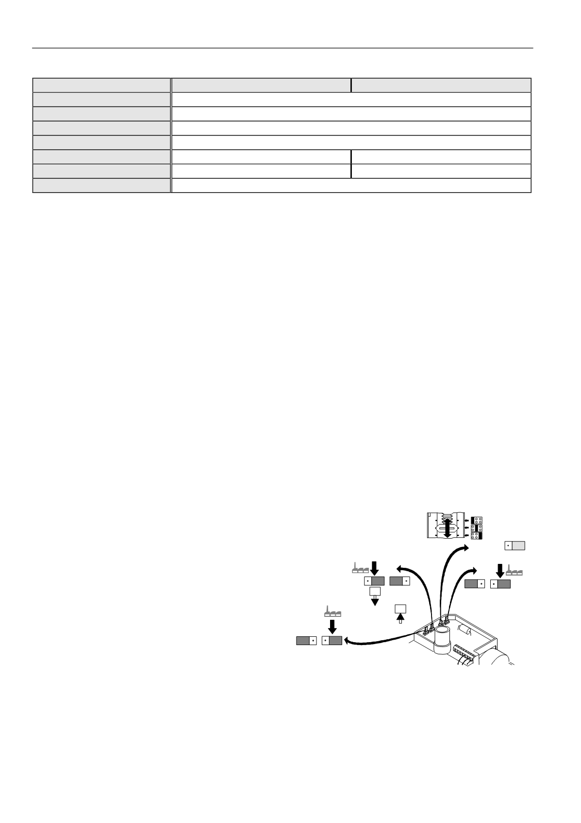
Input signal Vdc ormA is selectable by jumper plugW4
(Fig. 1.). The factory set is at Vdc. No external resistor for
mA-input signal is necessary.
Input Signal Range
The range of the analog input signal Y (0...10Vdc / 0...20mA
or 2...10Vdc / 4...20mA) can be selected by changing the
position of jumper plugW2 (Fig. 1.). The factory set is at
0...10Vdc.
Directionof Action
The direction of action (direct or reverse) can be selected by
changing the position of jumper plugW3 (Fig. 1.). The factory
set is: stem extends at increasing signal (direct acting).
NOTE:
Jumper plugsW1,W2,W3 andW4 are accessible
after the cover has been removed. They are lo-
cated on top side of the printed circuit board (see
Fig. 1.).
Fig. 1. Jumper plugsW1,W2,W3,W4
100
0
100
0
2...10V
4...20mA
W2
0...10V
0...20mA
10V
20mA
W3
10V
20mA
mA
W4
V
W1
(W4 )
V


